Chelsea PTO Installation & Operations Guide
How P.T.O.s Work: Gears, Gear Pitch and Ratio
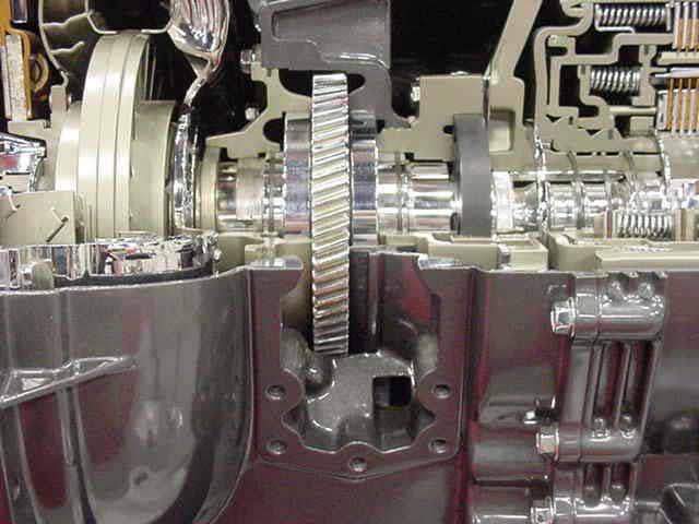
The typical Chelsea P.T.O. is designed to pick up engine power, through rotation, and transfer it to another piece of equipment. They are mechanical gearboxes that attach to an opening provided on truck transmissions and are used to transfer the power of the vehicle engine to auxiliary components, most commonly a hydraulic pump. The hydraulic flow generated by the pump is then directed to cylinders and/or hydraulic motors to increase performance. This page will explain important terms for your Chelsea PTO installation and operation.
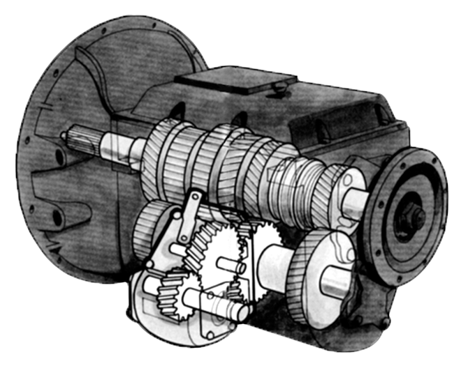
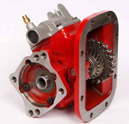
Side Mount PTO
You can download the Chelsea PTO Operations Guide by clicking here.If you need assistance identifying your Chelsea PTO parts contact our experts at 877-776-4600 or 407-872-1901 or visit our parts manuals page.
Click to enlarge
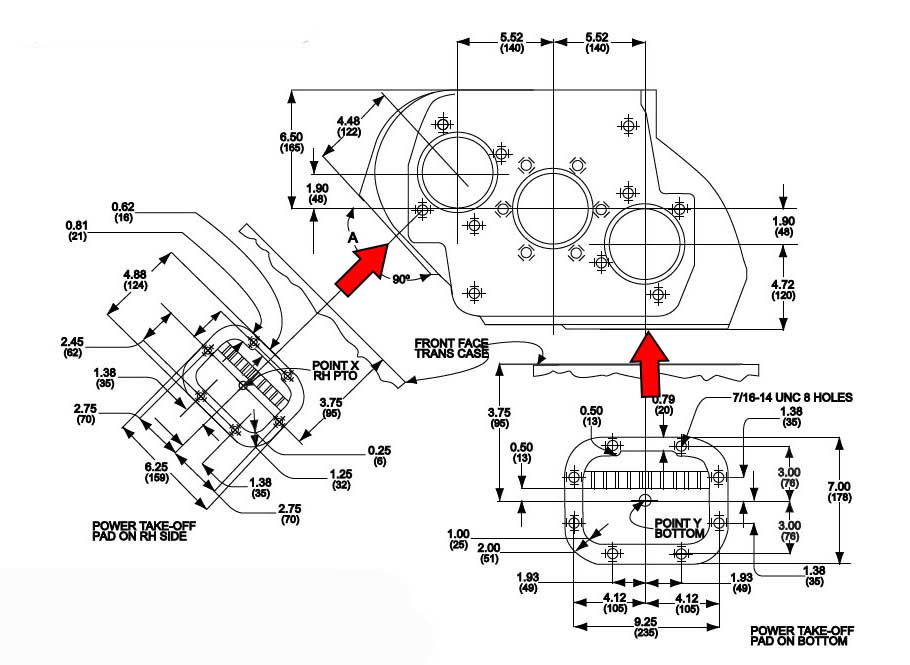
PTO placement for Eaton Fuller transmission
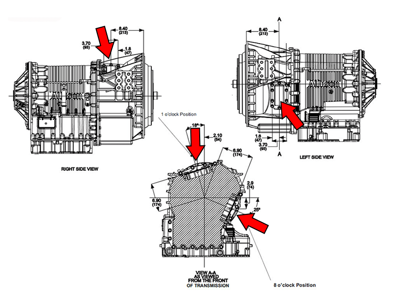
PTO placement for Allison transmission
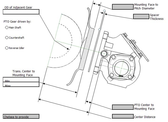
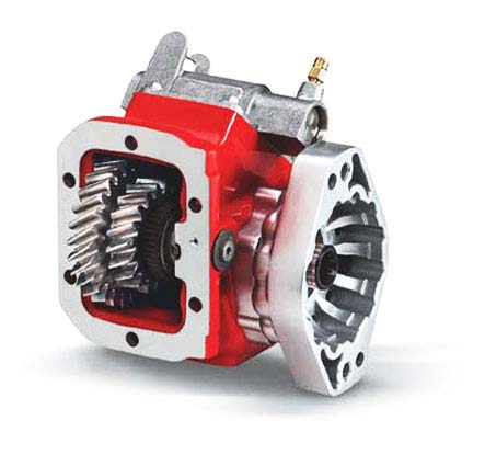
The most important part of a PTO installation is the gear, or gear set design.
Rotation is picked up by gears meshing or mating with other gears, in order for the Chelsea P.T.O. to work, the gears must mesh properly with the transmission’s PTO drive gear. When doing a PTO installation, it is very important, to know the design and specifications of the gear teeth in the transmission.
Important Power Take-Off terms
Spur Gear
 A gear whose teeth are cut straight across the face of the gear.
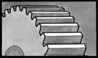
Helical Gear
 Gear whose teeth are cut on an angle diagonally across the gear either with a right or left-hand slant.
RIght/Left Handed Gear
 Helical gears may have their teeth with a right-handed or left-handed slant.
Pitch Diameter
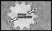 Distance across the center of the gear measured from the pitch line of one tooth to the pitch line of the tooth directly opposite that tooth
Pitch (Gear)
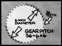 Measure of the size of the gear teeth determined by the number of teeth in a given area measured at the pitch line. P.T.O. gear pitch is normally classified as
5, 6 or 7-pitch
Pressure Angle
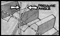 Angle formed, measured in degrees, by a line drawn perpendicular to the pitch line, and a line drawn from the same point on the pitch line tangent to the tooth profile.
Gear Ratio
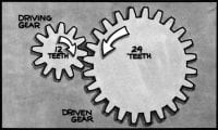 The gear ratio is determined by dividing the number of teeth in the driven gear by the number of teeth in the driving gear
(24 ÷ 12 for a gear ratio of 2 to 1).
Pitch Line
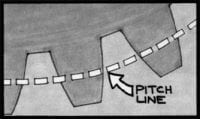 The point on the gear tooth midway between the base of the tooth and the tip of the tooth.
Pitch Line Velocity
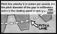 The speed of rotation in feet per minute of a gear measured at the pitch line, calculated by velocity V, in meters per second, d is the pitch diameter of the gear in millimeters and n is the rotating speed in rpm: V=πdn/6000.
- A spur gear will not mesh properly with a helical gear
- Helical gears not only must mesh with each other, but one must be right-handed and the other must be left-handed
- Helical gears also must have the same tooth construction in terms of pitch, pressure angle and helix angle
- Helix angle is the degree of the angle cut across the gear
- Gear ratio is another important part of P.T.O. operation. The P.T.O. gear ratio can actually modify the operating speed of the engine to the requirements of the P.T.O.-driven device
- The proper P.T.O. model has the necessary torque capacity and operating speed that most clearly meets the needs of the application
- Although the gear ratio in the example given above is 2 to 1, the change in torque is 1 to 2. This is arrived at by dividing the number h in the driven gear: 12 ÷ 24 = 0.5 (1 to 2).
Assume the engine horsepower is 50 and the speed of the small gear is 1000 revolutions per minute (R.P.M.).
The formula for determining torque is:
T = Horsepower x 5252 Speed (R.P.M.)/Speed (R.P.M.)
(SM) 50 x 5252 = 262.6 lbs. ft. Torque / 1000
(LG) 50 x 5252 = 525.2 lbs. ft. Torque / 500
NOTE:
If however, the situation was reversed with the larger gear driving the smaller gear, the smaller gear would rotate twice as fast as the larger gear, but the torque would rotate twice as fast as the larger gear, but the torque would only be half as great.
Equipment
PTOs are used in many applications. Common equipment types that benefit from a PTO are; dump trucks, dump trailers, bucket/man lift trucks, aerial lift trucks, fire and rescue trucks, refuse trucks, vacuum sucker trucks, sewer cleaner trucks, water/product pump trucks, propane delivery trucks, snow plow/dump trucks, gradall excavators, tow trucks and more.


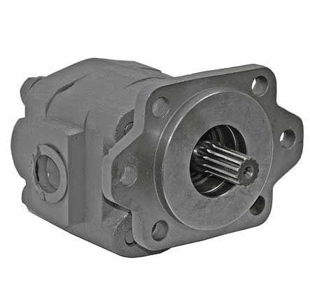
PTO Installation to the pump
Use caution to ensure that the bracket does not pre-load pump/P.T.O. mounting
The most common power take-off in use is the sidemounted PTO, there are also models installed to the rear of specific transmissions and split shaft PTOs that are mounted by removing a section of the vehicle’s main driveline.
Rear-mounted PTOs are often called countershaft PTOs but many sidemounted PTOs are also driven by gears on the transmission’s countershaft. You may hear people refer to side countershaft and rear countershaft power take-offs to make a distinction. The transmissions commonly found in class 4 and larger vehicles will have provisions for the PTO installation.
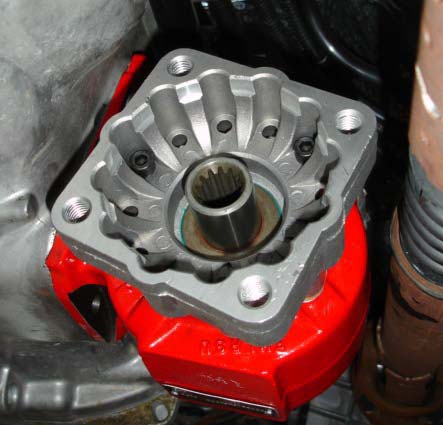
Generally there are two apertures, one on each side of the transmission(some smaller transmissions may have one). Many Eaton Fuller transmissions have a PTO aperture on the bottom (offset to the left), and some Allison automatic transmissions have a top aperture.
Your Chelsea PTO may be engaged by a cable, lever, air pressure, or hydraulic pressure. Recent PTOs use a small electric motor and hydraulic pump inside the shift cover assembly to provide hydraulic force to engage the PTO. There are various output shaft configurations available for a driveshaft connection or the pump attachment, directly to the PTO, without an intermediate shaft. The Society of Automotive Engineers (S.A.E.) has established standard mounting face dimensions for pumps and PTOs are made to accept these. These are referred to, from smallest to largest, as the S.A.E. A, B, D, E and F
S.A.E. “B” 2 & 4 Bolt Pump
S.A.E. “B” 2 & 4 Bolt Fixed Flange
S.A.E. “B” 2-Bolt Rotatable
S.A.E. “B” 4-Bolt Rotatable
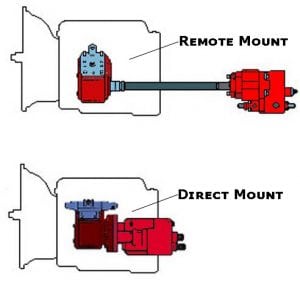
In a direct mount the hydraulic pump is mounted directly to the output flange of the PTO. Direct mounting is the most common type of PTO in the mobile equipment industry. A concern to be wary of when direct mounting a pump is a condition known as shaft fretting. This is rapid spline wear of the PTO and pump shafts. The wear is evident at the place in which the two metal surfaces come into contact with each other, as the micro-movement of the two surfaces against one another wears each surface. When direct mounting a pump you must do the following:
- Specify a PTO output shaft and mounting flange that match those of the pump.
- Select the correct pump rotation to match the PTO output rotation or select what is known as a bi-rotational pump, which tends to have equally sized ports since either can be the inlet or outlet.
- Provide a rear pump bracket to support the weight of the pump.
Sometimes it is not possible to direct mount a hydraulic pump, requiring the pump to be attached using a remote mount method. In a remote mount the pump is away from the PTO and powered from the power take-off by using a driveline assembly. Solid shafting is not recommended because it can’t be balanced and can vibrate. This leads to damage to the PTO and pump shaft seals. A balanced, tubular assembly designed to meet the speed, torque and horsepower requirements of the application is the best choice.
If using a driveline, it’s important for it to be in phase and incorporates a slip yoke at one end. Round, keyed PTO output shafts are susceptible to failure by high cyclic loading. An out of phase shaft will vibrate and damage the PTO and pump shaft seals while a functioning slip yoke will allow the shaft to adjust for flexing of the truck chassis.


Direct Mount DIN Flange


Driveshaft / Remote Mounts
Supporting the pump
Chelsea strongly recommends the use of pump supports (Support Brackets) in all applications.
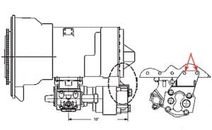
When using a direct mount method, in PTO installation, use a support bracket to support the pump to the transmission when the following conditions apply:
- The pump weight 40 pounds or more
- The combined length of the PTO and pump reaches or exceeds 18 inches from the PTO centerline to the end of the pump
ALSO: Remember to pack the female pilot of the P.T.O. pump shaft with grease before installing the pump on the P.T.O. (reference Chelsea grease pack 379688)
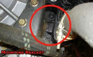
NOTE: For proper bracketing, attach at 2 or more transmission bolt locations and 2 or more pump locations. Contact transmission manufacture for proper bracket mounting locations. Use caution to ensure that the bracket does not pre-load pump/PTO mounting.